The Magic NEG pump
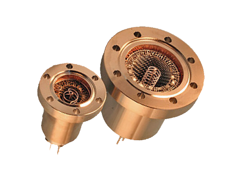
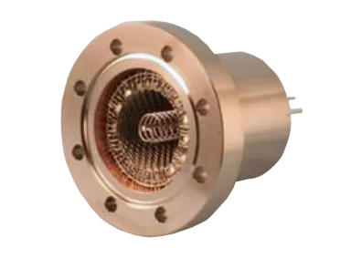
is a new getter pump architecture designed to enhance pumping capacity in the extreme-high vacuum (XHV) range. The pump’s materials and structural design have been optimized to significantly reduce hydrogen outgassing from the pump itself. By combining the Magic NEG pump with either a turbomolecular pump (for open systems) or a small ion pump (for sealed systems) as an auxiliary pump, it is possible to achieve XHV levels on the order of 10-10 Pa within 24 hours of starting from atmospheric pressure.
Features
- Low gas emission
- Place the NEG on the wall of the pump casing
- 0.2% BeCu alloy casing
- Expand effective pumping speed to 10-10Pa
- High pumping speed for CO (same as H2)
- No vibration, uncharged grain, no power (in operation)
- Flange type: DN40 (ICF70) & DN63 (ICF114)
- Any orientation
Specifications
| Item \ Product | DN40 (ICF70) | DN63 (ICF114) |
|---|---|---|
| H2 & CO pumping speed, L/s | 60~70 | 150~180 |
| N2 pumping speed, L/s | 20~25 | 60~70 |
| NEG materials | ZrV Fe | ZrV Fe |
| ∅10h3: number of Pills | 40 | 105 |
| Power, W [for SS] | 23 [40] | 40 [80] |
| Weight, g | 650 | 2,000 |
| Heigh, mm | 66 + 52 | 82 + 52 |
The difference from previous NEG pumps
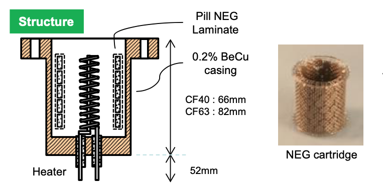
is that the array of NEG elements has been moved from the center of the vacuum port to the vacuum wall side surfaces. Many pill NEG elements are stacked in a cylindrical shape on the inner wall of a pump casing made of 0.2% BeCu alloy. The NEG elements are supported by a double mesh of stainless steel to prevent them from breaking. Since these NEG elements and steel meshes have a large thermal emissivity, they highly efficiently absorb the heat from the heater which is placed on the axis and readily heat up. In contrast, the pump casing is a copper alloy with a low emissivity that reflects and does not absorb virtually all of the radiative heat. Furthermore, the stainless steel mesh has an extremely low thermal conductivity and a gap of 1 to 2 mm, and also acts as a thermal insulator. This kind of mechanism prevents the pump casing from heating up and makes it possible to save power on activating the NEG. → This is called ‘the magic effect’ at our company.
The NEG elements are pill NEG of 10 mm diameter
The NEG material is the ternary alloy Zr(70%),V(24.6%),Fe(5.4%). After crushing into a powder of several 10s to several 100s of microns, the powder is tightly consolidated into a pill shape without binder using the ratio of particle sizes as a mechanism. As a result, the pills have a gas transmissible porous quality with a wide surface area that adsorbs gas. The pills from our company are hard and feature small powder shedding. The optimal activation temperature for this pill NEG is 450 to 500 °C, and the time is 30 to 60 min. The pill size used in the magic NEG is standardized to the relatively large diameter of 10 mm with the aim of reducing cost and assuring quality.
The pumping characteristics of the magic NEG pump
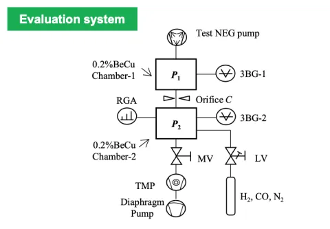
were measured using the apparatus shown in the right diagram. The pumping speed S can be found using the following Eq. (1).
- S=C [ (P2-P2u) / (P1-P1u) -1 ] , P1u, P2u : Ultimate vacuum Eq. (1)
NEG pump performance evaluation method:
The NEG pumping mechanism differs completely between H2 and Co/N2. Since H2 diffuses through the NEG bulk, it causes virtually no decrease in exhaust speed as pumping continues. However, when CO or N2 are pumped, they cover the NEG surface and the pumping speed drops (is returned to the initial value by reactivation). Because of this, graphs of the pumping speed S which show the performance of the NEG typically show the accumulated value Qt (m ⋅Pa) on the horizontal axis. However, since there is virtually no degradation by CO or N2 in the XHV region, the characteristics can be more easily understood by showing the horizontal axis in normal pressure (Pa). Furthermore, when S is found from Eq. (1), it extends to low pressures of 10-11 Pa that have not actually been measured and tends to create the false impression that it can pump down to the XHV range. In order to prevent this misconception, our company uses the method of also showing the value found from Eq. (2) S = C (P2/P1 – 1) for effective pumping speed without subtracting the ultimate vacuum.
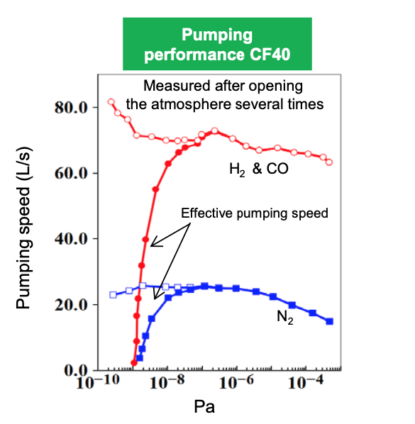
The pumping characteristics of magic NEG114
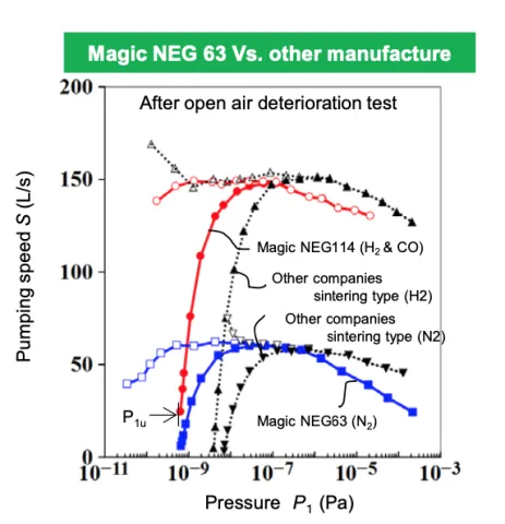
are shown in the following graph (see reverse for CF40). The curves for 〇 and □ show the values found using Eq. (1), while ● and ■ show the values found using Eq. (2). With Eq. (2), S becomes zero around 1×10⁻⁹ Pa. This is because [NEG pump exhaust]=[Self-gas emission from NEG pump]. Although the pressure at which S becomes zero in the XHV region also varies depending on the emission velocity of the gas being pumped, in all NEG pumps it becomes zero around 1×10⁻⁹ Pa. The ▲ and ▼ markers in the graph show the S curves plotted using Eq. (2) when the NEG pump (latest sintered model) of a competitor company with virtually the same pumping speed was studied using the same measurement apparatus. Although the shape of the curve resembles that for the magic NEG, the minimum of S for the competitor sintered model occurs at around 4 to 6×10⁻⁹ Pa, whereas for the magic NEG114 (CF63) this was an order of magnitude lower at 6×10⁻¹⁰ Pa. We believe that this difference appears as a result of the magic NEG pump having measures for reducing self-gas emissions. If the XHV that can be generated by the NEG pump is considered as the point where the ultimate vacuum at pumping speed S reaches zero, then confirming the ultimate vacuum of the S curve under no load is an important point when choosing an XHV-NEG pump!
